
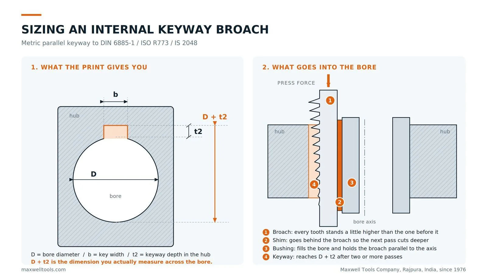
A keyway broach is not chosen, it is derived. The bore diameter fixes the key width from the parallel key standard, the standard fixes the depth of the keyway in the hub, and the number you actually broach to is the bore diameter plus that depth, measured straight across the bore. Bushing size, the number of passes and the press tonnage all fall out of those figures and the length of the bore.
The chart below gives the sizes for broaching this profile. The rest of this guide covers the parts of the job that the chart does not: which tolerance class the broach has to be ground for, why the bore length quietly sets a limit on the tool, how to size the bushing and shim stack, and how to work out whether the press in your shop can actually pull the cut. Maxwell Tools has been making broaches to component drawings since 1976, and most of the problems below are ones we see on enquiries and on returned tools.
The three numbers that define a keyway broach
Every keyway broach comes down to three figures.
- Width of cut. Set by the key width b from the standard, and held to a tolerance class, not to a nominal size.
- Total depth of cut. Set by the hub keyway depth t2, delivered over one, two or three passes.
- Maximum length of cut. Set by how much chip the gullets can hold, not by how long the tool is.
The first two come off the print in a minute. The third is the one that gets skipped, and it is the usual reason a broach snaps or a keyway comes out with a torn finish at one end. It is covered further down.
Keyway broach size chart, metric bores
Nominal parallel key and keyway sizes by bore diameter. These values are common to DIN 6885-1, ISO/R 773, BS 4235-1 and IS 2048, which agree across this range.
| Bore diameter D (mm) | Key b x h | Broach width | Hub depth t2 | Broach to (across bore) |
| over 6 up to 8 | 2 x 2 | 2 mm | 1.0 +0.1 | D + 1.0 |
| over 8 up to 10 | 3 x 3 | 3 mm | 1.4 +0.1 | D + 1.4 |
| over 10 up to 12 | 4 x 4 | 4 mm | 1.8 +0.1 | D + 1.8 |
| over 12 up to 17 | 5 x 5 | 5 mm | 2.3 +0.1 | D + 2.3 |
| over 17 up to 22 | 6 x 6 | 6 mm | 2.8 +0.1 | D + 2.8 |
| over 22 up to 30 | 8 x 7 | 8 mm | 3.3 +0.2 | D + 3.3 |
| over 30 up to 38 | 10 x 8 | 10 mm | 3.3 +0.2 | D + 3.3 |
| over 38 up to 44 | 12 x 8 | 12 mm | 3.3 +0.2 | D + 3.3 |
| over 44 up to 50 | 14 x 9 | 14 mm | 3.8 +0.2 | D + 3.8 |
| over 50 up to 58 | 16 x 10 | 16 mm | 4.3 +0.2 | D + 4.3 |
| over 58 up to 65 | 18 x 11 | 18 mm | 4.4 +0.2 | D + 4.4 |
| over 65 up to 75 | 20 x 12 | 20 mm | 4.9 +0.2 | D + 4.9 |
| over 75 up to 85 | 22 x 14 | 22 mm | 5.4 +0.2 | D + 5.4 |
| over 85 up to 95 | 25 x 14 | 25 mm | 5.4 +0.2 | D + 5.4 |
| over 95 up to 110 | 28 x 16 | 28 mm | 6.4 +0.2 | D + 6.4 |
| over 110 up to 130 | 32 x 18 | 32 mm | 7.4 +0.2 | D + 7.4 |
Two warnings on this table.
- DIN 6885-2 is a different pattern. It seats the key deeper in the shaft and shallower in the hub, so t2 is roughly half the figure above for the same key. If the drawing calls DIN 6885-2, this table will give you a keyway that is far too deep.
- The depth tolerance is one sided and positive. On keys up to 6 mm wide it is +0.1 and 0, and from 8 mm up it is +0.2 and 0. You can be deep by that much and be right. You cannot be shallow by anything.
For inch work the equivalent standard is ASME B17.1, which is still current under stabilised maintenance. The method below is identical, only the numbers change.
The dimension you actually broach to
Take a 40 mm bore with a 12 mm keyway to DIN 6885-1.
- 40 mm falls in the 38 to 44 band, so the key is 12 x 8 and the broach is 12 mm wide.
- The hub keyway depth t2 is 3.3 mm, tolerance +0.2 and 0.
- The dimension to broach to is 40 + 3.3 = 43.3 mm, so anything from 43.3 to 43.5 is in tolerance.
That total, bore diameter plus t2, is the only depth figure worth putting on a setup sheet, because it is the only one you can measure reliably. There is no flat surface to reference t2 from. The mouth of the keyway sits on a curve, so a depth micrometer has nothing square to sit on and every operator will read it slightly differently. Measured across the bore, from the bore wall opposite the keyway to the keyway floor, with a telescoping gauge or a plug and a micrometer, the reading repeats.
On the shaft side the equivalent check is the shaft diameter minus the shaft keyseat depth. Same logic, opposite sign.
Broach width is not the same as key width
The chart says 12 mm. The hub keyway is not 12 mm, it is 12 mm to a class, and which class you need is a fit decision made by the designer, not a machining preference.
| Class | Fit in the hub | What it is for | Limits on a 12 mm keyway |
| D10 | Free | Key slides in the hub, sliding or adjustable joints | 12.050 to 12.120 |
| JS9 | Normal | The default when the print does not say otherwise | 11.979 to 12.022 |
| P9 | Close | Key is an interference fit in the hub, no backlash | 11.939 to 11.982 |
A broach ground to a bare 12.000 will produce a keyway that passes JS9 when the tool is new, drifts toward the bottom of the band as the flanks wear, and will never make D10 at all. The finishing teeth have to be ground for the class the drawing calls. A broach bought for JS9 work cannot be moved onto a D10 job without a different tool.
Because side wear only ever makes the cut narrower, a new broach is normally ground toward the upper half of the band so that wear does not immediately push parts out of tolerance. Measure the first component off a new or freshly reground tool before you release the batch. On the shaft side the matching classes are H9 free, N9 normal and P9 close.
Gullet capacity: the limit that breaks broaches
Every chip a tooth cuts has to sit in the gullet ahead of that tooth for the whole length of the pass. There is nowhere else for it to go and no way to clear it mid cut. Once a gullet packs, the chip is compressed against the workpiece, cutting force climbs steeply, the finish tears, and the tool can crack.
That puts a hard maximum on the length of cut for a given broach, and it is a design figure, not something you can push by feel. A standard keyway broach carries a maximum length of cut in its specification, and it is usually shorter than people expect. If your bore is longer than that figure, the options are:
- A broach designed for the job, with a coarser pitch and deeper gullets. This is the correct answer for production.
- Broach part way, retract, clear the gullets, then continue. Works, but slow and it can leave a witness line.
- Broach from both ends and finish the middle with a long bushing. It gets a one off out of the door and it is not a production method.
As a design rule, the tooth pitch is set at roughly 1.2 times the square root of the cut length in millimetres, with three to eight teeth in cut at any moment. Below three teeth the tool wanders and chatters. Above eight the force climbs enough to matter on a small press.
Sizing the bushing
The bushing does two things: it fills the bore so the broach cannot wander, and it takes the side load so the broach stays parallel to the bore axis. Get it wrong and the keyway runs out of parallel, which is the most common complaint on a broached hub.
- Outside diameter: 0.02 to 0.08 mm under the finished bore. It has to slip in without a hammer and without any rock.
- Collar: a flange on the top so it cannot be pushed through the part.
- Slot width: broach width plus about 0.05 mm. Tight enough to guide, loose enough not to bind on chips.
- Slot depth: set so the first tooth of the broach just starts to cut with no shim fitted. This is the datum for the entire shim stack. If it is wrong, every pass is wrong by the same amount and the keyway will be uniformly shallow or deep.
- Length: at least the length of the bore, and preferably longer, so the broach is supported both above and below the cut.
Free machining or leaded steel is fine and does not need hardening for anything short of high volume. If you make your own bushing, stamp the slot depth on the collar. A bushing with an unknown slot depth is scrap, because there is no way to work back to it once the broach is in.
Shims and the number of passes
Most keyway broaches do not reach full depth in one pass. The shim goes between the back of the broach and the floor of the bushing slot, pushing the tool further out into the workpiece for the next pass.
| Broach width | Normal number of passes | Shim rule |
| 2 mm to 4 mm | One, no shim | Full depth is ground into the tool |
| 5 mm to 14 mm | Two | One shim, thickness equal to one pass depth |
| 16 mm and above | Three or more | Stack shims, never thicker than one pass depth |
A shim must never be thicker than the depth the broach cuts in one pass. If it is, the leading teeth are forced to take a cut they were not ground for and the tool will chip or break.
A light final pass is worth having. It improves finish and evens out any depth variation from the first pass. But do not take it too light: below the minimum chip thickness the teeth rub instead of cut, which work hardens the surface and takes the edge off the finishing teeth faster than a proper cut would.
Working out the press force
The force is straightforward to estimate and worth doing before you buy a tool for a press you already own.
F = b x s x k x n
- b is the width of cut in mm
- s is the rise per tooth in mm, typically 0.03 to 0.08 on a keyway broach
- k is the specific cutting resistance in kgf per square mm: roughly 200 to 250 for cast iron, 250 to 300 for mild steel, 300 to 400 for alloy steel
- n is the number of teeth cutting at once, which is the cut length divided by the pitch, rounded up
Worked example. A 12 mm keyway in a 60 mm long bore in 4140, rise per tooth 0.05 mm, pitch 12 mm, k taken at 350.
- n = 60 / 12 = 5 teeth in cut
- F = 12 x 0.05 x 350 x 5 = 1050 kgf, about 1.05 tonne
- Allow a factor of 1.8 for a worn tool, friction on the bushing and thin lubrication, and you need about 1.9 tonne at the ram
So a 3 tonne press does that job comfortably and a 2 tonne press will stall once the tool has some wear on it.
Two things fall out of that formula that the catalogue will not tell you. First, a longer bore needs a bigger press for the same keyway, because n rises with bore length while everything else stays the same. Second, adding shims does not reduce the force. The rise per tooth is ground into the tool, so every pass pulls roughly the same load. If the press is genuinely too small, the ways to cut the force are to reduce the width of cut by roughing with a narrower broach first, or to remove most of the material another way, for example plunging an end mill down the bore before broaching so the tool only has to clean up the corners.
Getting the bore right before you broach
A broach follows the bore. It does not correct it, and a bore that is out of round or tapered will give a keyway that wanders in step with it.
Bore and ream to final size before broaching, not after. Broaching after a final hone will roll a burr into the finished bore.
- Chamfer both ends of the bore. A sharp bore mouth turns into a burr in the keyway corners.
- Broach in the soft condition. HSS keyway broaches work sensibly up to roughly 30 to 32 HRC and life falls away quickly above that. Harden and temper afterwards, and allow for growth.
- Use a proper broaching or heavy duty cutting oil. This is a single very heavy cut at low speed and the lubricant is doing most of the anti weld work.
- Support the part squarely on the press table with clearance underneath for the broach to exit.
- Never strike a broach with a hammer, soft faced or not. HSS at broaching hardness is notch sensitive and a blow will start a crack in a tooth root that you will not see until it fails.
When a standard broach will not do the job
A standard broach and bushing covers a good share of ordinary work. These are the cases where it does not, and where a tool has to be made to the component.
- Bore longer than the standard maximum length of cut
- A key width that is not on the standard list, or a width class the standard tool cannot hold
- DIN 6885-2 depths, or any drawing specified depth that is not the standard t2
- Two or three keyways at 180 or 120 degrees, which need an indexed bushing made with the tool
- Blind bores and stepped bores, where the broach cannot run out the far side
- Small bores below about 8 mm, where a standard broach and bushing will not both fit
- Square, hexagonal, rectangular, round and ratchet profiles, and internal splines and serrations, which are a different tool family altogether
Maxwell manufactures keyway broaches and special form broaches in both push and pull styles, in HSS M2, M35 and PM-HSS ASP 2030, made to component specification rather than to a catalogue list. Bushings and shims are made with the tool so the slot depth and the shim stack are matched from the start.
What to send with an enquiry
- Component drawing, or a sketch with the bore diameter and the bore length
- Keyway width and depth, and the width tolerance class if the drawing calls one
- Number of keyways and their angular positions
- Material and its hardness at the time of broaching, not after heat treatment
- Machine details: push or pull, stroke, and the tonnage available
- Pull end or holder type, if it is a pull broach
- Quantity, because it changes whether M2, M35 or ASP 2030 is the right steel
With those seven items a broach can be quoted and drawn without a single follow up question, which is usually the difference between a two day and a two week quotation.
Frequently asked questions
What size keyway broach do I need for a 25 mm bore?
A 25 mm bore falls in the 22 to 30 mm band, so the standard parallel key is 8 x 7 mm and the broach is 8 mm wide. The hub keyway depth t2 is 3.3 mm with a tolerance of +0.2 and 0, so you broach to 28.3 mm measured across the bore.
How do you measure the depth of a broached keyway?
Across the bore, not down from the bore surface. The figure is the bore diameter plus the hub keyway depth t2. Measure from the bore wall opposite the keyway to the floor of the keyway, using a telescoping gauge or a plug and a micrometer. There is no square surface to reference a depth micrometer against at the mouth of the keyway, so a direct depth reading will not repeat.
How many passes does a keyway broach need?
Up to about 4 mm wide, usually one pass with no shim. From about 5 to 14 mm, two passes with one shim. From 16 mm up, three or more. The shim must never be thicker than the depth the broach cuts in a single pass.
What size should a broach bushing be?
The outside diameter is 0.02 to 0.08 mm under the finished bore, the slot is the broach width plus about 0.05 mm, and the slot depth is set so the first tooth just begins to cut with no shim fitted. The bushing should be at least as long as the bore, and longer if the press setup allows it.
What press tonnage do I need for keyway broaching?
Multiply the width of cut in mm by the rise per tooth in mm by the specific cutting resistance of the material in kgf per square mm by the number of teeth in cut, then allow a factor of about 1.8 for wear and friction. A 12 mm keyway in a 60 mm long alloy steel bore works out at roughly 1.9 tonne, so a 3 tonne press is the sensible minimum.
Can you broach a hardened part?
Not with an HSS broach in any practical way. Broach in the soft condition, up to roughly 30 to 32 HRC, then harden and temper. If the part is already hardened, the keyway has to be produced by wire EDM or by grinding instead.
The takeaway
The size chart is the easy part. What decides whether a broached keyway is right is the depth you measure to, which is the bore diameter plus t2 and never t2 on its own; the width class the finishing teeth are ground for; and whether the bore is short enough for the gullets on the tool you are holding. Get those three right and the bushing, the shims and the press follow without argument.