
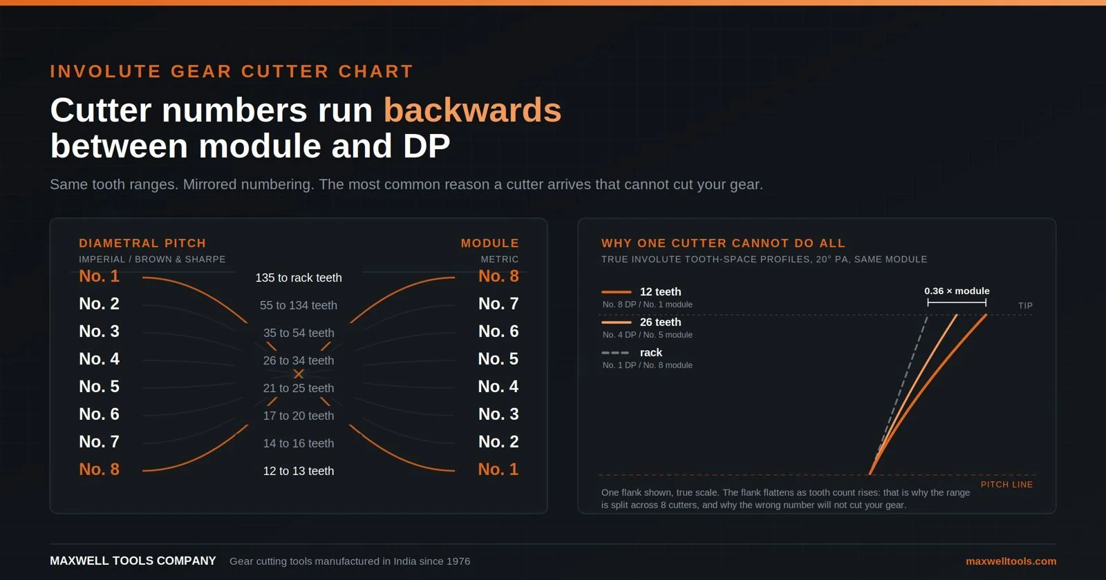
Quick answer: A standard involute gear cutter chart divides the whole range from a 12 tooth pinion up to a rack across 8 numbered cutters. In the imperial diametral pitch (Brown and Sharpe) system, No. 1 cuts 135 teeth to rack, and No. 8 cuts 12 to 13 teeth. In the metric module system the numbering runs the opposite way: No. 1 cuts 12 to 13 teeth, and No. 8 cuts 135 teeth to rack. The tooth ranges are identical. The numbers are mirrored. This is not a marking fault, and it is the most common reason a buyer receives a cutter that cannot cut the gear on the drawing.
If you take one thing from this involute gear cutter chart, take this: never order a gear cutter by its number alone. Order by module or DP, by pressure angle, and by the tooth range printed on the cutter face. The number is a shorthand, and the shorthand is not universal.
The two involute gear cutter charts
Chart 1: Diametral pitch (imperial, Brown and Sharpe) cutters
| Cutter No. | Cuts gears with |
| 1 | 135 teeth to rack |
| 2 | 55 to 134 teeth |
| 3 | 35 to 54 teeth |
| 4 | 26 to 34 teeth |
| 5 | 21 to 25 teeth |
| 6 | 17 to 20 teeth |
| 7 | 14 to 16 teeth |
| 8 | 12 to 13 teeth |
Chart 2: Module (metric) cutters
| Cutter No. | Cuts gears with |
| 1 | 12 to 13 teeth |
| 2 | 14 to 16 teeth |
| 3 | 17 to 20 teeth |
| 4 | 21 to 25 teeth |
| 5 | 26 to 34 teeth |
| 6 | 35 to 54 teeth |
| 7 | 55 to 134 teeth |
| 8 | 135 teeth to rack |
Read the two charts side by side and the pattern is immediate. The tooth bands are the same. The numbering is mirrored. A No. 3 imperial cutter and a No. 3 module cutter are different tools and will not produce the same gear.
This is why the same argument has run on machinist forums for two decades over whether imported module cutters are stamped backwards. They are not. They follow the metric convention, which counts upward from the smallest tooth count, while Brown and Sharpe counted downward from the rack. Each system is internally consistent. Neither is defective. What is wrong is the assumption that one universal numbering exists.
Why cutter numbers exist at all
A form milling cutter is a fixed shape. It machines the gap between two teeth, and the shape of that gap is whatever profile the cutter carries. Hobbing is different: it generates the flank through coordinated motion and one hob covers every tooth count at a given module. Form milling simply reproduces the cutter’s own profile in the workpiece.
The difficulty is that the correct tooth space is not one shape. An involute flank unwinds from the base circle, and base circle diameter equals pitch diameter multiplied by the cosine of the pressure angle. Fewer teeth give a smaller base circle and a tightly curved flank. More teeth give a larger base circle and a flatter flank. At an infinite tooth count, meaning a rack, the flank becomes a straight line.
So the theoretically correct cutter for a 13 tooth pinion and the correct one for a 200 tooth wheel are visibly different shapes. Grinding a separate cutter for every possible tooth count is not commercially sensible, so the span from 12 teeth to a rack is divided into 8 bands and one cutter serves each band.
Two consequences follow, and both matter at the machine:
- Only one tooth count in each band receives a theoretically exact profile. By established convention each cutter is formed to suit the lowest tooth count in its range. Gears near the top of a band therefore finish with slightly thinner teeth and a little extra backlash rather than teeth that bind. That bias is deliberate, because surplus clearance is recoverable and interference is not.
- Form milling is always an approximation. For general machinery, repair work, one-off replacements and low volume batches, the deviation sits well inside what the application tolerates. Where speed, load or running noise are critical, hobbing or shaping is the correct process and a numbered form cutter is not.
How to read what is stamped on the cutter
A properly marked cutter carries everything needed to identify it without any chart at all. Look for:
- Pitch: a module value (M2, MOD 2, m=2) or a diametral pitch value (12 DP, 12P, 12 D.P.)
- Pressure angle: 14.5°, 14½°, 20°, or 30° on spline forms
- Cutter number: No. 4, #4
- Tooth range: printed as a span, for example 26 to 34
The tooth range is the authoritative marking. A cutter stamped “M2, 20° PA, No. 5, 26 to 34” cuts 26 to 34 tooth gears in module 2, whatever any chart says about number 5. The printed range overrides the number every time.
Where the range is missing or worn away, use the pitch marking to decide which convention applies. A cutter marked in DP follows Chart 1. A cutter marked in module follows Chart 2. Cutters made to order sit outside both systems and should carry their range explicitly.
The pressure angle trap
A widespread default catches people out: module cutters are commonly supplied at 20° pressure angle, and older imperial DP cutters were commonly 14½°. Many suppliers lean on that default and mark the pressure angle only when it departs from it.
Treat the default as a hint and never as a fact. A 14½° cutter and a 20° cutter of the same pitch and number generate different flank angles, and the resulting gears will not mesh correctly with each other. Confirm the pressure angle from the marking or from the drawing before any metal is cut, and when replacing a gear inside an existing assembly, take it from the mating gear rather than from assumption.
The 15 cutter half number chart
Where profile accuracy has to be tighter than an 8 cutter set delivers, the imperial system offers an extended chart with half numbers, splitting each band roughly in two:
| Cutter No. | Cuts gears with |
| 1 | 135 teeth to rack |
| 1½ | 80 to 134 teeth |
| 2 | 55 to 79 teeth |
| 2½ | 42 to 54 teeth |
| 3 | 35 to 41 teeth |
| 3½ | 30 to 34 teeth |
| 4 | 26 to 29 teeth |
| 4½ | 23 to 25 teeth |
| 5 | 21 to 22 teeth |
| 5½ | 19 to 20 teeth |
| 6 | 17 to 18 teeth |
| 6½ | 15 to 16 teeth |
| 7 | 14 teeth |
| 7½ | 13 teeth |
| 8 | 12 teeth |
Notice how sharply the bands narrow at low tooth counts. That is not arbitrary. The involute changes shape fastest when there are few teeth, so profile error from spreading one cutter across a wide band grows quickly at the small end. If you cut pinions below roughly 20 teeth and the gear matters, the half number set earns its cost. Above 55 teeth the flank is close enough to straight that the standard 8 cutter set is normally adequate.
Helical gears: the correction most charts leave out
When you form mill a helical gear with a standard involute cutter, you do not select on the actual tooth count. Select on the virtual, or equivalent, tooth count. The cutter travels through the gear along the helix and sees a section that behaves like a larger gear.
Zv = Z ÷ cos³β
where Z is the actual number of teeth and β is the helix angle.
Worked example: 30 teeth at a 20° helix angle
- cos 20° = 0.9397
- 0.9397³ = 0.8298
- Zv = 30 ÷ 0.8298 = 36.2, round to 36
A 30 tooth spur gear takes an imperial No. 4 cutter (26 to 34). This helical gear takes an imperial No. 3 (35 to 54). One number out, and the tooth form is wrong.
A more extreme case: 20 teeth at a 30° helix angle
- cos 30° = 0.8660
- 0.8660³ = 0.6495
- Zv = 20 ÷ 0.6495 = 30.8, round to 31
That shifts you from a No. 6 cutter to a No. 4, two full numbers. Pick on the actual tooth count here and the gear is scrap.
Two further points on helical work. The cutter must match the normal module or normal DP, not the transverse value. And the space cut will be wider than the cutter because of the helix, so tooth thickness needs verifying over pins or by span measurement rather than assuming it came out nominal.
Can you get away with the wrong cutter number?
Sometimes, and it is worth being precise about when.
- One number away, above 55 teeth: usually workable. The flank is nearly straight in this region and the profile deviation stays small. Expect a little more backlash or slightly rougher running.
- One number away, below 25 teeth: generally not acceptable for anything carrying load. Profile error concentrates at root and tip, the contact pattern shifts, and noise and pitting follow.
- Which way to err, if you must: take the cutter for the lower tooth band. That gives a slightly thinner tooth with extra clearance. Going to the higher band risks a fatter form that interferes at the tip and binds.
- Never substitute across pressure angles or pitches: neither is recoverable. A 20° cutter will not produce a usable 14½° gear at any tooth count.
For a change gear, a hand crank, a restoration piece or a lathe banjo gear, the compromise is often acceptable. For a gearbox running continuously it is not, and the correct answer is either the right cutter or a different process.
Module to DP conversion
Module and diametral pitch describe the same quantity from opposite directions: m = 25.4 ÷ DP, and DP = 25.4 ÷ m.
| DP | Equivalent module | Nearest standard module |
| 4 | 6.35 | 6 |
| 6 | 4.233 | 4 |
| 8 | 3.175 | 3 |
| 10 | 2.54 | 2.5 |
| 12 | 2.117 | 2 |
| 16 | 1.588 | 1.5 |
| 20 | 1.27 | 1.25 |
| 24 | 1.058 | 1 |
| 32 | 0.794 | 0.8 |
| 40 | 0.635 | 0.6 |
| 48 | 0.529 | 0.5 |
The third column is for identification only. Do not substitute a near module for a DP gear inside a working mesh. Module 0.8 and 32 DP are close (31.75 DP against 32 DP) and get swapped often in model engineering, but across a full gear train the accumulated pitch error shows up as noise and uneven wear. In production work, cut to the system the drawing specifies.
What to send when you order
An involute gear cutter chart answers which number you need. It does not answer everything a manufacturer needs from you. Whether you are buying a standard cutter off the shelf or a custom form, this is the complete data set. Supplying all of it removes every ambiguity discussed above:
- Module or diametral pitch, and which of the two it is
- Pressure angle (14.5°, 20°, 30°, or other)
- Number of teeth on the gear to be cut
- Gear type, spur or helical. If helical, the helix angle and the hand
- Workpiece material and hardness
- Bore diameter and keyway required
- Quantity, and whether you need a full set or individual numbers
- Any drawing, sample gear, or photograph of an existing cutter marking
Items 1 to 4 on their own are enough for us to determine the correct number in either convention, which means the numbering question never has to be resolved at your end.
Maxwell Tools Company has manufactured gear cutting tools in Rajpura, India since 1976 and exports to over 50 countries. Send your gear data or drawing and we will confirm the cutter number in both systems before you commit to an order. Full specifications, materials and module range are on our gear cutters product page.
Frequently asked questions
Which cutter number do I need for a 25 tooth gear?
In the imperial DP system, No. 5, which covers 21 to 25 teeth. In the metric module system, No. 4, which covers that same 21 to 25 tooth band. Confirm from the tooth range printed on the cutter, not from the number.
Why is my module cutter numbered the opposite way to the chart I found?
Most published charts show the Brown and Sharpe imperial convention. Module cutters follow the metric convention and count in the reverse direction. Both are correct inside their own system.
Are imported gear cutters marked wrong?
Usually not. Module cutters count upward from 12 teeth. Buyers comparing them against an imperial involute gear cutter chart conclude the marking is reversed, when in fact the cutter follows a different and perfectly valid convention. Check the tooth range span on the cutter face and the disagreement resolves itself.
Does the tooth range change with pressure angle?
No. The banding is the same for 14.5° and 20° cutters within a given system. The ground profile differs between the two, but the ranges each number covers do not. Pressure angle and pitch must still match your gear exactly.
How many cutters are in a full set?
Eight cutters span 12 teeth to a rack for one pitch and one pressure angle. An extended 15 cutter set using half numbers is available where tighter profile accuracy is needed, particularly on low tooth counts.
Can one cutter produce every gear of the same module?
No. The involute flank shape changes with tooth count because the base circle diameter changes, so a set of 8 is the minimum to cover the full span at acceptable accuracy.
Which number do I use for a helical gear?
Select on the virtual tooth count, Zv = Z ÷ cos³β, not the actual tooth count, and match the cutter to the normal module or normal DP.